Liebherr LTM11200-9.1 Mobile Crane
"Mammoet"
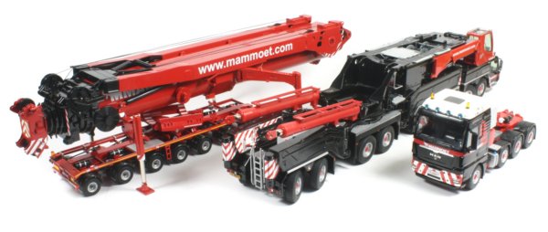
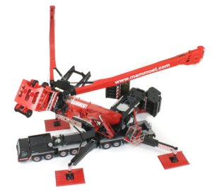
Presented here is the 1:50th scale Liebherr LTM11200-9.1 telescopic boom mobile crane in Mammoet livery from NZG. In my opinion, this is without a doubt one of the best models NZG have ever produced with a level of detail and realism found in every aspect of the model, from the crane mats and choice of lattice boom heads to the fully functional boom support system, nothing has been missed.
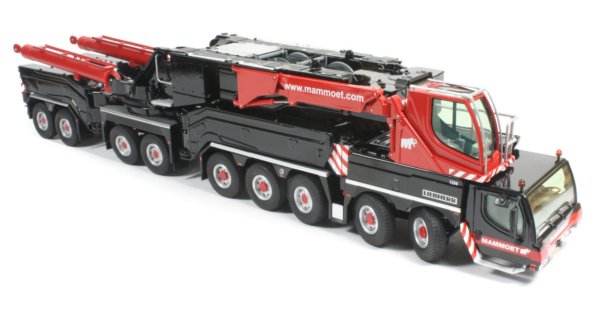
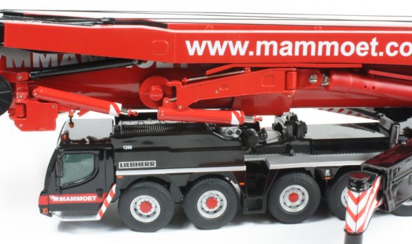
Each of the nine axles features spring loaded, pivoting suspension and functional steering with the angle of steering movement very respectable for such a large and heavy model. There are two different styles of silver wheel hubs with red highlighted centres which are fitted with Michelin branded rubber tyres that have an accurate tread pattern.
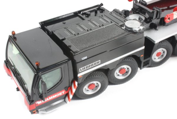
The main cab is low mounted at the front of the chassis and has a replicated interior with rear view mirrors, windscreen wipers and roof mounted amber beacons all fitted. The carrier's engine compartment is located behind the cab and has textured grill panels cast into the surfaces with silver exhaust and air coolers all present.
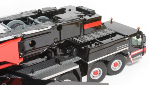
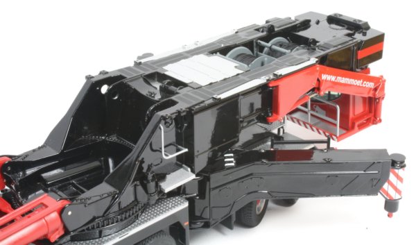
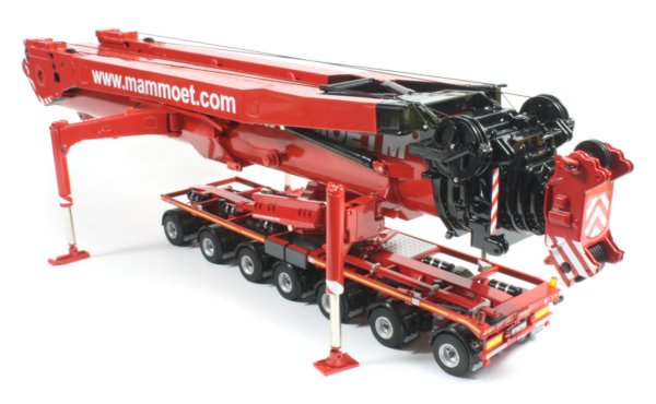
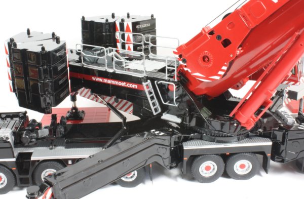
In transport configuration, the super structure can be positioned either forward or rearward and a nice touch are the white detailed wear strips on each of the outrigger arms where the large lift cylinders rest. The two main winches are housed centrally in the frame with the rear most floating so that it can rest lower during transport and raises once the counterweight tray is fitted. The winches are operated by inserting the supplied winding keys into the holes in the side of the super structure. The rear deck has a silver finished access ladder and diamond plate textured panels with a non-opening storage box and cradle fitted to the inside of the arms.
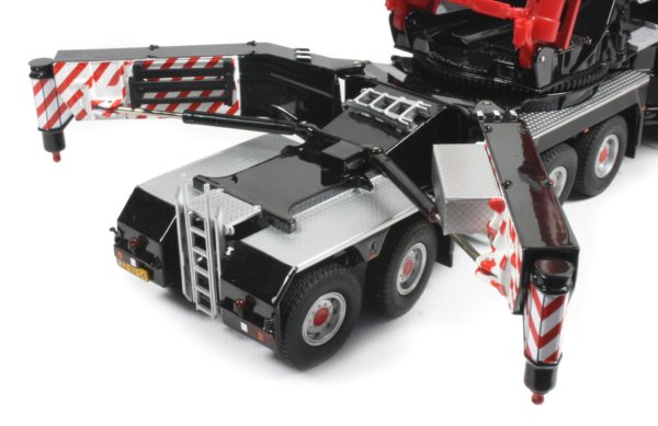
The four outriggers extend out from the carrier into an X pattern with telescoping sections giving a large area for good stability. This is needed as the telescopic boom is incredibly heavy and the model is likely to tip over without the outriggers fully extended. The inside surfaces of the arms have a red and white chevron pattern printed on them, extending to the ends of each jack. The screw thread is hidden within so the jacks look very realistic with a smooth silver piston look as they are extended, added to by the use of ball joint tips that fit into the four pads and are locked into place with small pins which is a great touch on the model.

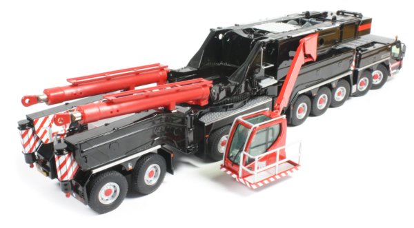
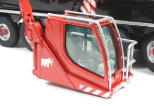
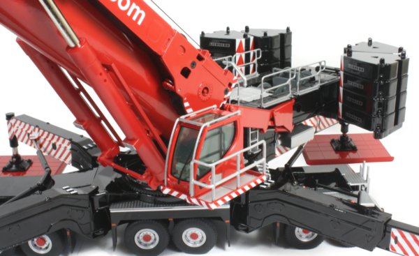
The counterweight tray connects to the model utilising two screws which need to be secured on the underside of the super structure. This is not the easiest part to assemble and needs the screws to be firmly secured to hold the weight of the metal counterweight stones, sixteen of which are supplied. The crane cab is fitted to an arm mounted to the super structure which rotates almost 180 degrees with a parallel linkage allowing the cab to be lowered to the ground for added safety for the operator.
|
|
This is fully functional on the model with the ability to store the cab at the rear of the crane or above the front cab depending on the configuration of the 360 degree rotating super structure. The cab tilts by about 30 degrees to give a better view of the work area and a small access platform with silver handrails is fitted to the side of the cab, which has an accurately replicated interior. |
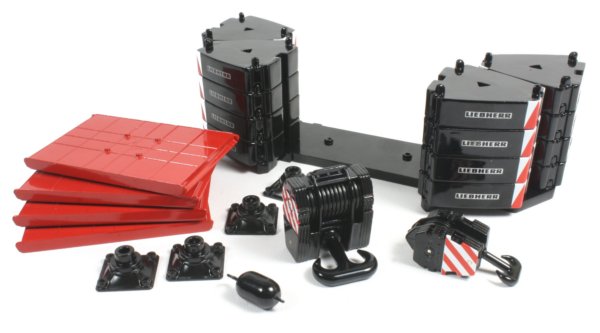
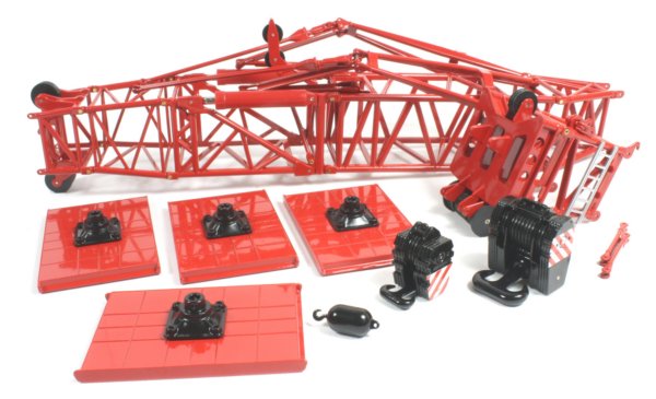
As well as the four small pads for the stabilisers, NZG have also included four large metal crane mats which is a very welcome addition. There are also three different sized hook blocks and sixteen triangular shaped counterweight segments, each with small cast lugs allowing them to lock together. Small Liebherr logos are printed on each piece along with red and white chevron pattern on the tips.
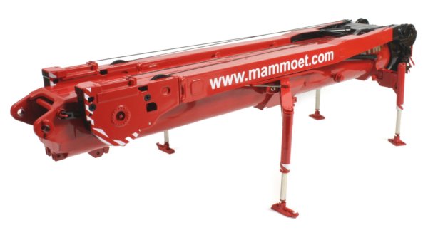
The telescopic boom is exceptionally heavy, with almost everything made from metal. Just lifting it out of the box, you appreciate the fine detailing and functionality, from the fully modelled and working boom lift system to the detailed boom head and seven smoothly extending boom sections. Once all the packing material is removed, the four jacking legs swing out into place with the larger legs having small bars which lock them in place. The smaller legs click into place and the weight of the boom when resting on the legs prevents them from collapsing which is a nice touch.
The four jacks rotate to extend them and once you get them turning, they rotate smoothly with the screw thread hidden inside. The tips have a ball shape which fits snugly into the pads and small pins lock them in place. This again shows the fantastic level of detail NZG have engineered into the model. Two of the pads have simulated adjustment hydraulics which are used on the real crane to do fine positioning of the boom.
Connecting the boom to the carrier is easier than it looks, although it is a good idea to remove the hydraulic connection screws from the boom before you start. Once the boom is positioned in place, two large metal pins can be inserted to secure the base of the boom with the super structure. There are small clips that can be used to lock the pins in place to prevent them falling out if required. (Note, the boom carrier trailer pictured here is a separate model from WSI and not included with the LTM11200-9.1)
The next step is to position the main lift hydraulics and re-insert the screws. The boom is now fully connected to the carrier and can be raised. The hydraulics are very stiff and have two sets of holes in them where a pin can be inserted to keep the boom raised. Without extending the boom, the hydraulics will just about hold the boom at a lower angle but probably not for long.
Once the boom is secured, the four lifting jacks can be raised and the pads removed so they can be folded up against the side of the boom and out of the way (Pictured above). While not shown, the four lifting jack structures can be disconnected from the boom completely by removing the metal pins.
|
|
The telescopic boom sections have been modelled to allow different configurations of the crane to be built, with the third section having the connection points to connect the heavy lift boom head (pictured left) A nice feature of this is that you don't have to remove the other boom sections when setting up in this configuration. |

The head of the seventh boom section has metal pulley shieves which rotate freely along with connection points for the lattice jib assembly supplied in the box. The lattice jib is already assembled with small nut and bolts holding the parts together. The two large hydraulic pistons allow the angle of the jib to be adjusted and these are quite stiff to adjust. There are also two support bars which fold out and connect to the tips of the rope guying system, just like on the full sized crane.
The super structure has a number of safety rails which need adding along with the exhaust stack and side access ladders which fit well. A note of caution, the two small hand rails at the front can get damaged if they are fitted before the boom is raised if the Y guying arms are not extended out.
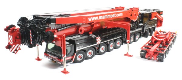
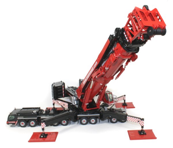
This model is fast becoming my favourite crane model, partly because of the excellent level of engineering to get everything to function like the full sized crane and partly because of the accessories allowing different configurations to be constructed. For those collectors with room, the model looks great with the boom fully extended and the Y guying system deployed.
|
The Y guying system is fully working on the model with the large arms lifting and extending out hydraulically, with the hydraulics stiff enough for the arms to remain in position. Each arm has a small winch which is operated using the supplied winding key to adjust the rope to tension the boom when it is extended. The arms are connected to the base of the boom with a metal rope assembly which accurately simulates the actual metal strands fitted to the real machine. |
|
The paint finish is of a very high standard throughout with accurate placement of the Mammoet markings. The inside surfaces of the main stabiliser leg is particularly well decorated with the chevron pattern following the contours of the casting. The model is also very well packed in a three section polystyrene carton holding everything secure which slides into a printed cardboard box. The Mammoet version is limited to only 600 pieces and comes with a small certificate.